Yes, my EV is actually running!
A little peek under the hood...
I know that it has been an extremely long time since my last post...all I can say is work is crazy and any free time that I have was spent getting this EV running.
I have lots of great people to thanks including Stephen from HPEV, South Seattle Community College (Murray and class), and good friends Chad and Jared.
I plan to post a lot of content to this blog in July during my vacation.
Sent from my iPhone
Sunday, May 16, 2010
Saturday, July 11, 2009
Build Session 24 (180 mins): Drilling and Mounting the Adapter Plate
This weekend Jared and I broke away from work long enough to drill the
six mounting bolt holes in the adapter plate. Then we mounted the
steel adapter coupling with the key pin and a bolts. After that we
attached the spline assembly.
I ordered the adapter plate assembly from EV America...primarily because they were the only ones at the
time that were selling a clutch-less adapter plate design. I like the concept of a clutch-less design because every pound of rotational weight equally approximately 100 pounds of total weight. So reducing
rotational weight should extend the overall range of my EV.
Jared drilling the first hole...We're using a 1/2 in corded drill with a 31/64 drill bit.
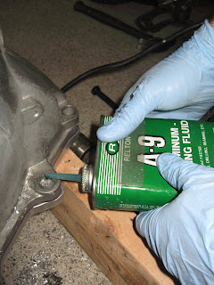
We used a fair amount of aluminum cutting oil to speed our progress and save our bit...
After drilling each hole we bolted it together to ensure that the adapter plate wouldn't move. To connect the adapter plate I purchased 4 9.8 grade 80mm M12 bolts, nuts, washers, and lock washers and 2 100mm bolts. I plan to use the longer ones to attached torque rods if needed.
After drilling the first four holes and bolting each to the bell housing, we removed the C clamps and drilled the remaining two holes.
Drilling complete...
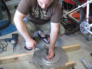
After that we removed the adapter plate and disassembled the hub assembly from the adapter plate by knocking out the long pins. EV America ships the coupler disk, steel hub, and adapter plate pinned together with long pins to ease alignment for marking and drilling. Now its time to remove the long pins and replace them with short pins that hold the couple disk and hub assembly together only.
KIDS PLEASE NOTE: Flip flops are NOT appropriate protective clothing for working on electric vehicles! At least I have safety glasses on. :)
Then inserted the coupler disk hub assembly over the spline transmission shaft and took some measurements with the digital calipers. This measurement helped us to figure out where to bolt the steel hub on the motor shaft.
Jared double checking his measurements...
This is what the coupler disk hub assembly from EV America looks like when dissembled. The splined hub on the left is a new Chevy S10 clutch disc that I sent them. They remove the friction material and then bolt and pin it to the their coupler disk / steel hub assembly. The splines connector in the clutch disc is need to mate with the transmission shaft.
Realizing that we didn't want to disassemble the coupler hub assembly just yet, we put it back together, place it on the motor shaft with key, and used our previous measurements to position the hub.
With the shaft key already in place, we put some lock-tite on the bolts and tightened the steel hub in place.
Now its time to remove the clutch disc and the aluminum coupler assembly from the steel hub. This will allow us to slide the spacers and the adapter plate over the steel hub and bolt them into place.
Double checking the steel hub bolts to make sure that they are tight. Yes, that is blue painter tape protecting my motor from damage and shavings.
After sliding the spacers disks and the adapter plate over the steel hub we bolted it into the motor with four 3/8 by 2 3/4" grade 8 bolts, washers, lock washers, and some locktite.
Once again we reassembled the coupler disk assembly to the steel hub. Yes, more locktite...
And finally we reattached the clutch disc with 8 bolts and locktite...
Its beautiful! Its ready to bolt to the transmission...but that's all the time I have for today. :)
Labels:
adaptor plate,
Advanced DC,
Chevy,
Drill,
Electric Motor,
EV,
EV America,
Motor Adaptor,
s10
Saturday, June 20, 2009
Build Session 23 (240 mins): Shaping the Adapter Plate
I decided to hold off on the dual motor setup for now in hopes of getting this truck up and running this year.
This weekend Jared, Chad, and I marked and cut the 1/2 inch adapter plate that connects the transmission bell housing to the motor adapter.
We used the Rigid band saw with a 3/4 inch Lenox Bi-Metal blade and a LOT of aluminum cutting oil. The cutting was slow going but the end result was worth it. After cutting we cleaned up the edges with the grinder, wire wheel, and a little filing. During the next build session we will drill the holes and bolt the bell housing to the adapter plate.
The adapter plate before we cut...
The cutting is slow...Chad keeps the blade plenty lubed with aluminum cutting oil which definitely saved the blade.
We used to brush to keep the oil where we wanted it...
Still cutting hours later...
Pretty good for a 3/4 inch band saw blade...
I'm grinding down the rough cuts...
Chad decided to hand file a bit.
Perfect fit...I like it. Its ready for drilling during the next build session.
Labels:
Aluminum,
Band Saw,
Electric Motor,
Electric Vehicle,
EV,
Lenox,
Motor Adaptor,
Rigid,
Transmission
Friday, June 12, 2009
Build Session 22 (60 mins): Another Coat of POR-15
Jared and I added a coat of POR-15 Chassis Coat black on top of the epoxy paint. The Chassis Coat provides UV protection (fade resistance) on top of the rust preventing epoxy coat.
Friday, June 5, 2009
Build Session 21 (180 mins): Epoxy Painted Battery Racks and Frame
This weekend Jared, Chad, and I had a productive painting session. In a couple of hours we managed to finish the welding on the rear battery racks. Then we painted the rear battery racks, rear differential, and frame with POR-15 Epoxy paint which should keep them from rusting.
Jared and my welding helmets.
Jared and Chad painting. Chad is a good friend of ours. He just graduated from High School, is an invaluable robotics club member on the team that we mentored and is a skilled machinist. Not bad for a teenager!
Starting from the inside and working our way out...
Remember how many months ago we spent a whole day prepping the frame with scrub brushes and the pressure washer...I think it was about a year ago. Wow, time fly's.
I even painted the frame underneath after laying out plastic on the driveway an taping plastic around the cab.
The epoxy paint goes a long ways and looks great.
Nice...
It looks amazing!
Chad got some POR-15 epoxy on himself...It should wear off in a few weeks. Sorry Chad. :)
Wednesday, June 3, 2009
Zilla Z2K Controller Finally Arrived!
Yes, it has been over six months since I have posted! I have been extremely busy with work and mentoring a high school robotics team. School is out and robotics is over for now. Work is still extremely busy but several EV discussions with my good friend Jared has helped motivate me to spend a little bit of time each week on the project...regardless of work deadlines. I hope to continue making progress and posting the results on a more regular basis.
But that's not the purpose of this post. If you haven't already guess from the title of this post...drum roll please...yes, after almost eight months of waiting THE ZILLA HAS ARRIVED!!! It makes me happy. :)
But that's not the purpose of this post. If you haven't already guess from the title of this post...drum roll please...yes, after almost eight months of waiting THE ZILLA HAS ARRIVED!!! It makes me happy. :)
Labels:
Electric Motor,
EV,
Motor Controller,
Z2k,
Zilla
Saturday, November 1, 2008
Battery Box Layout Diagram
I'm still busy with family activities, at work, and with various projects as a mentor of the Tahoma Robotics Club so I currently have very little time to work on this project. However, the good new is that my batteries are on order! Specifically, 50 ThunderSky 160 amp hour batteries. Initially, I plan to use 48 of them at 3.2 volts nominal each for a total of 153.6 total volts. I have been working with Manzanita Micro and they have agreed to order the batteries for me. My original plan was to order the TS batteries direct from China but I dreaded the hassle of getting them through customs. Manzanita Micro has experience ording these cells as they use them in their prius hybrid kits. So, I sent them a check and now I wait. The lithium batteries may arrive this year although it won't slow me down any if they don't since my Zilla controller won't be ready until May or June. And so I must be patient...
I created a diagram for those of you who are interested in some of the dimensions and layout of the battery boxes. The 48 ThunderSky cells will completely fill the forward twin battery boxes under the lift bed and a little over half of the rear battery box, leaving me some room for expansion in the future. With 48 of the 160 amp hour cells the total traction pack will contain over 24,000 kwh. I estimate that this will provide me with a range of 100 plus miles at my average daily driving speeds. But only time will tell...
Notice the red motors in the diagram with not tranmission. I have done a lot of research lately on the possiblity of building a direct drive system. Which basically means connecting the motor or motors directly to the drive line and eliminating the transmission completely. Many people that I have contacted say it can't or shouldn't be done while others seem to disagree. John (coworker and former race car builder/driver) and I have completed many calculations on this subject and have determined that two WarP / Impulse 9 inch motors connect in series will provide ample torque even on hills at slow speeds when controlled by my Zilla and its parallel / series capabilities. So, I am tentatively planning to move forward with this plan and may put an order in for a couple of Impulse 9 motors at the end of this year. I'll keep you posted...
Labels:
batteries,
EV,
LiFePO4,
lithium iron phosphate,
manzanita micro,
s10,
thunder sky,
thundersky
Subscribe to:
Posts (Atom)


