six mounting bolt holes in the adapter plate. Then we mounted the
steel adapter coupling with the key pin and a bolts. After that we
attached the spline assembly.
I ordered the adapter plate assembly from EV America...primarily because they were the only ones at the
time that were selling a clutch-less adapter plate design. I like the concept of a clutch-less design because every pound of rotational weight equally approximately 100 pounds of total weight. So reducing
rotational weight should extend the overall range of my EV.
Jared drilling the first hole...We're using a 1/2 in corded drill with a 31/64 drill bit.
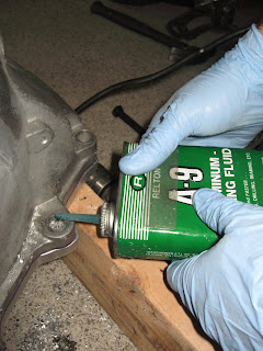
We used a fair amount of aluminum cutting oil to speed our progress and save our bit...
After drilling each hole we bolted it together to ensure that the adapter plate wouldn't move. To connect the adapter plate I purchased 4 9.8 grade 80mm M12 bolts, nuts, washers, and lock washers and 2 100mm bolts. I plan to use the longer ones to attached torque rods if needed.
After drilling the first four holes and bolting each to the bell housing, we removed the C clamps and drilled the remaining two holes.
Drilling complete...
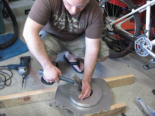
After that we removed the adapter plate and disassembled the hub assembly from the adapter plate by knocking out the long pins. EV America ships the coupler disk, steel hub, and adapter plate pinned together with long pins to ease alignment for marking and drilling. Now its time to remove the long pins and replace them with short pins that hold the couple disk and hub assembly together only.
KIDS PLEASE NOTE: Flip flops are NOT appropriate protective clothing for working on electric vehicles! At least I have safety glasses on. :)
Then inserted the coupler disk hub assembly over the spline transmission shaft and took some measurements with the digital calipers. This measurement helped us to figure out where to bolt the steel hub on the motor shaft.
Jared double checking his measurements...
This is what the coupler disk hub assembly from EV America looks like when dissembled. The splined hub on the left is a new Chevy S10 clutch disc that I sent them. They remove the friction material and then bolt and pin it to the their coupler disk / steel hub assembly. The splines connector in the clutch disc is need to mate with the transmission shaft.
Realizing that we didn't want to disassemble the coupler hub assembly just yet, we put it back together, place it on the motor shaft with key, and used our previous measurements to position the hub.
With the shaft key already in place, we put some lock-tite on the bolts and tightened the steel hub in place.
Now its time to remove the clutch disc and the aluminum coupler assembly from the steel hub. This will allow us to slide the spacers and the adapter plate over the steel hub and bolt them into place.
Double checking the steel hub bolts to make sure that they are tight. Yes, that is blue painter tape protecting my motor from damage and shavings.
After sliding the spacers disks and the adapter plate over the steel hub we bolted it into the motor with four 3/8 by 2 3/4" grade 8 bolts, washers, lock washers, and some locktite.
Once again we reassembled the coupler disk assembly to the steel hub. Yes, more locktite...
And finally we reattached the clutch disc with 8 bolts and locktite...
Its beautiful! Its ready to bolt to the transmission...but that's all the time I have for today. :)


3 comments:
Very impressive! Thanks for the safety message.
Kurt! You haven't posted for awhile now. Get back at it ;-) Your project has helped me move mine along as you can see here
Lance - Unfortunately work has kept me too busy to work on this project. I am hoping to make more progress in the next month or two but we'll see. Thanks for the poke and the link. Perhaps I can use your site to help me finish. :)
Post a Comment